airfoil simulator
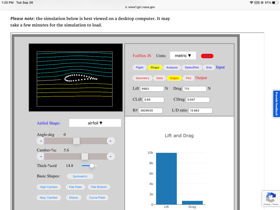
FoilSim is a NASA website that is free to use. The purpose of using an airfoil simulator is to test and change different components of an airfoil to find the most efficient design. Using a simulator, the thickness, camber, wing span, basic shape, and chord can be changed regarding the airfoil's shape and size. To test the airfoil, the velocity, altitude, and angle of attack can be changed to simulate different conditions an airfoil may fly in. From these tests, the simulator can analyze the lift to drag ratio as well as the performance under varying conditions.
Using Excel
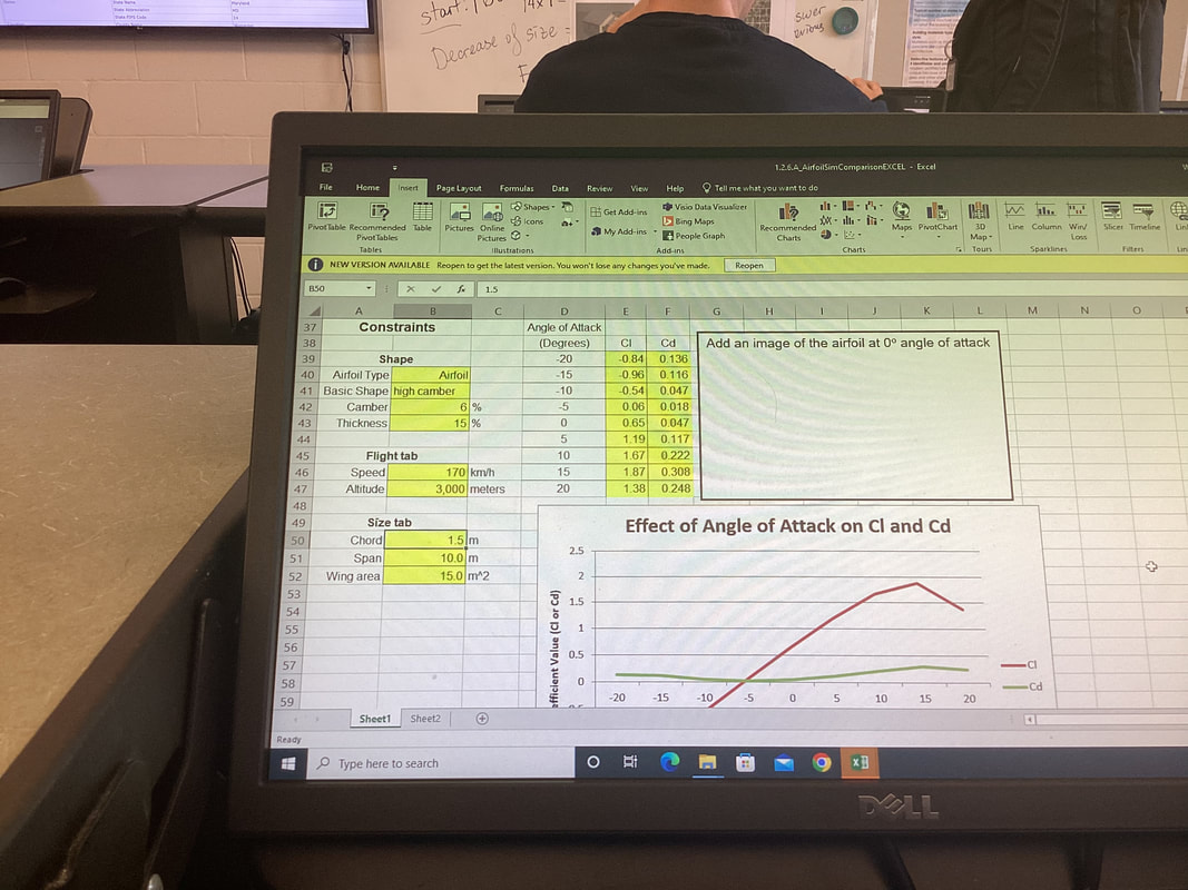
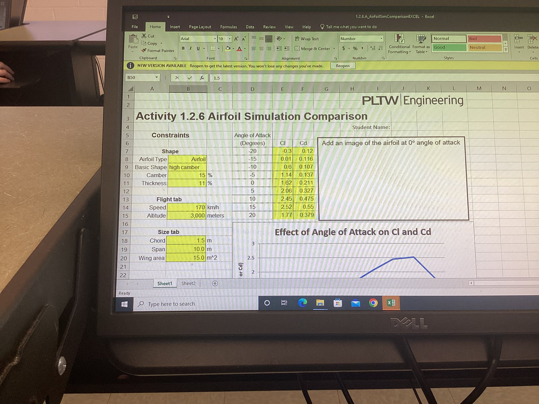
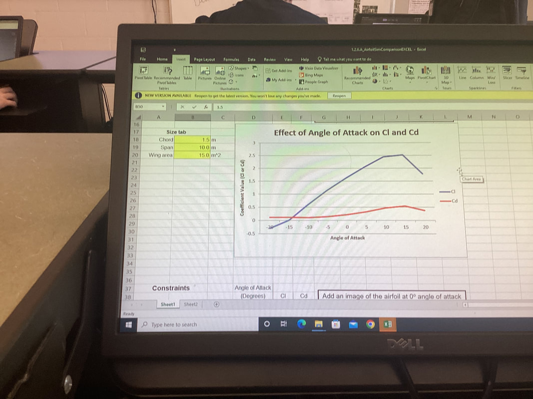
Before starting my official airfoil design, we had done an investigation with two different airfoil designs to find which would be more efficient. My first airfoil that I tested was a high camber airfoil. It had a camber of 15%. The lift to drag ratio was very large, which wasn’t very efficient. This is because even at a negative angle of attack, the airfoil still generated a positive lift to drag ratio which would be problematic if an aircraft was attempting to land but couldn’t descent since there’s too much lift. My second airfoil design was also a high camber airfoil, except it had a camber of 6%. This design was much more efficient than the previous because it still had a high lift to drag ratio but it wasn’t generating positive lift at a negative angle of attack. To compare both of the airfoils in excel, I copied the lift to drag ratio at certain degrees of angle of attack, both negative and positive. I then created a table in excel and used the values to make a chart. The chart I created showed the relationship between the angle of attack and the lift to drag ratio. This helped me decide which design was more efficient because it helped me to see when the lift to drag ratio became positive, at what rate would the amount of lift increase as the degree of angle of attack increased, and at what angle the design would stall.
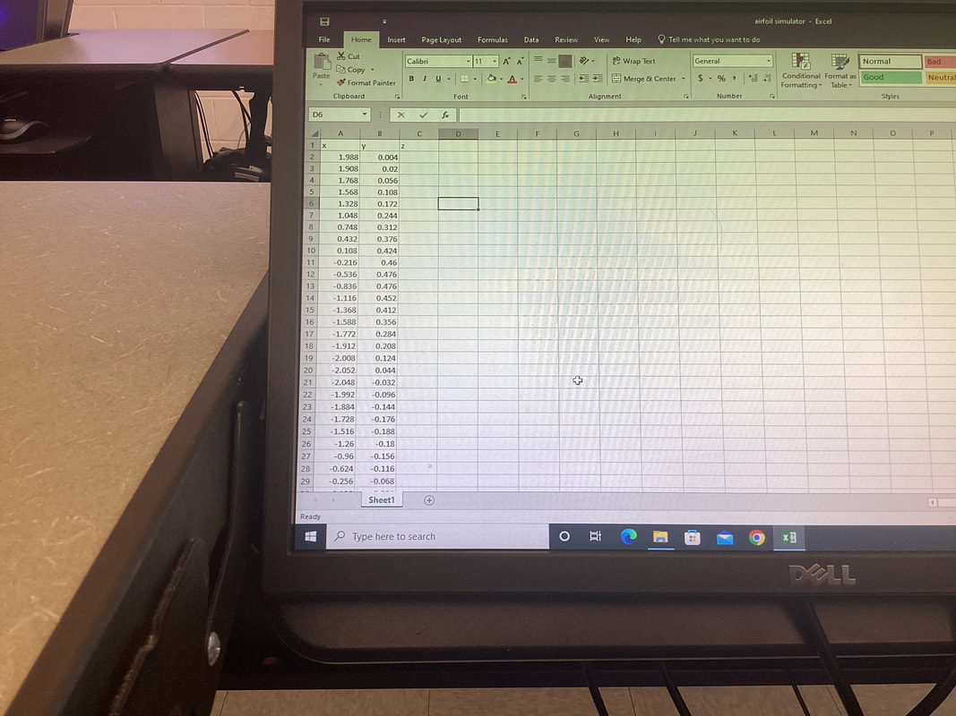
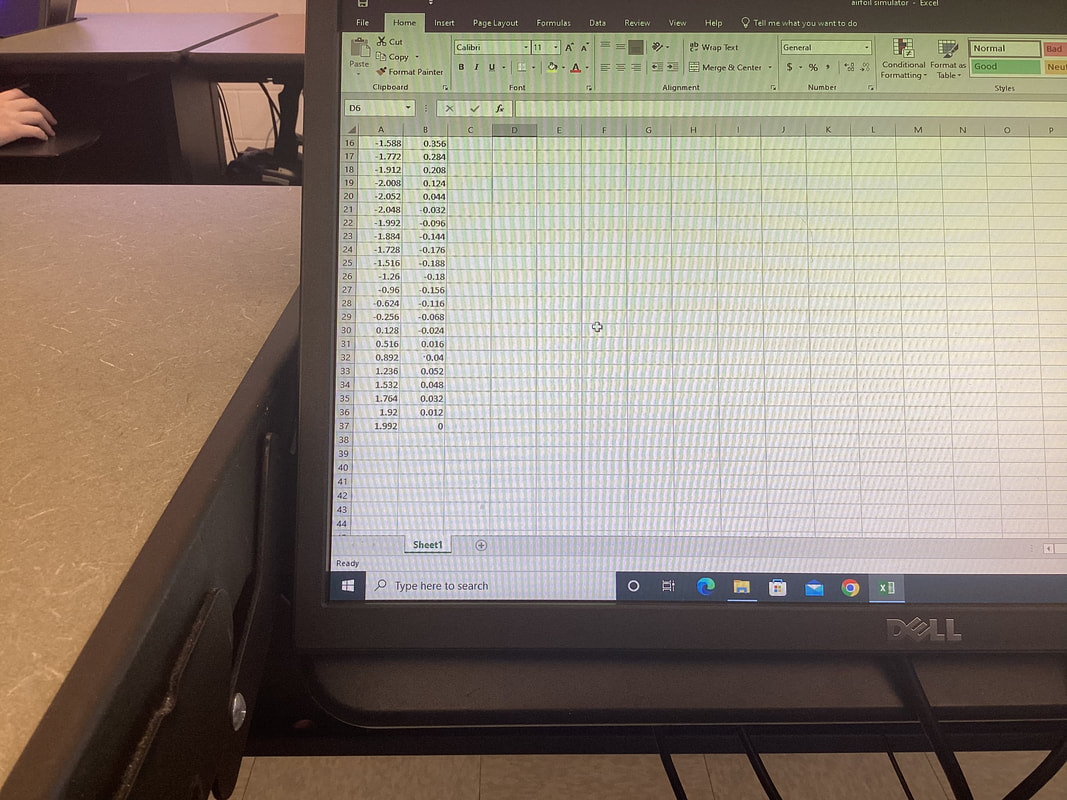
To create my airfoil in a format that would allow me to 3D print it, I first used the geometric points of my airfoil that were provided on FoilSim. I copied and pasted them into a table that I had created on Excel. For the table to work I had to go through and make sure the values were input as numbers and not words before taking the table and transferring it to inventor. I also had to make sure no points overlapped as well as making sure the top and bottom half of the airfoil points met at a common point to ensure there were no gaps in my airfoil sketch.
Once I transferred these to inventor, I created a sketch and added the table of values from excel. This plotted the points of my airfoil and from there I was able to connect all the points. Before extruding, I made sure there were no gaps in my airfoil and all my points were correct. Once I was sure of this, I extruded my design to the required width of the airfoil. I saved my file as a pdf and was finally able to 3D print the airfoil.
Once I transferred these to inventor, I created a sketch and added the table of values from excel. This plotted the points of my airfoil and from there I was able to connect all the points. Before extruding, I made sure there were no gaps in my airfoil and all my points were correct. Once I was sure of this, I extruded my design to the required width of the airfoil. I saved my file as a pdf and was finally able to 3D print the airfoil.
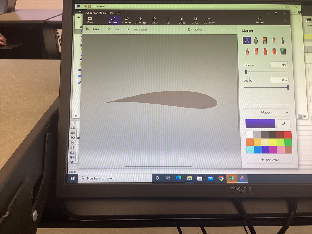
To construct my airfoil, I used the pdf file I created in inventor to send to the 3D printer. My design was 3D printed, and given more time, I would’ve sanded the edges to make sure the surface was smooth. Although the 3D printers were proving to be difficult when printing other designs, mine came out as it was intended on the first print. I do not have a picture of my printed airfoil since I did not get to test it.
Wind tunnel testing
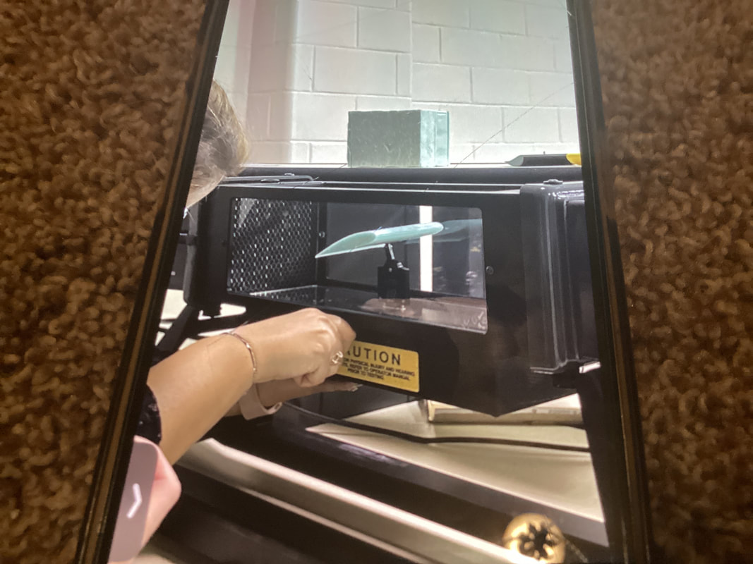
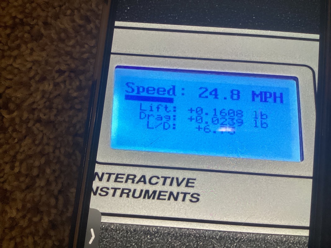
The purpose of a wind tunnel is to test the components of an aircraft to see if it functions properly, needs improvements, and if it is an efficient design. Since the wind tunnel tests components in a life like environment, it shows were the weaknesses are in the design so improvements can be made. After Testing an airfoil in the wind tunnel, I gathered data to compare to my excel chart. The designs of the airfoils are not the same, but are very similar as well as the data I collected. At 0 degrees angle of attack, the tested airfoil had a positive lift drag ratio of 6.73. This was similar to my design, which had a positive lift drag ratio at 0 degrees angle of attack as well. As the angle of attack decreased to -5 degrees, the tested design had a lift drag ratio of 0.3. Similarly, my design at -5 degrees had a positive lift drag ratio. When the angle of attack increased for the tested airfoil, the lift drag ratio kept increasing, a trend which is reflected in my design’s data as well.
|
|
|
Overall, I think I was successful in my airfoil design. Although, I did run into a few issues trying to save my files, I was able to find a way to download them and prevent my work from getting lost after several attempts. If I was to do this project again, I would’ve liked to test my design as well as get to sand it. I also would possibly change my airfoil design to see how something different would perform. The first step of the design process I used in this project is Identifying the problem. The task was given to us to create an efficient airfoil design within certain size constraints. Next, I used generate concepts to come up with design ideas for my airfoil. I knew more camber would give my design a good lift drag ratio, although I didnt want to have too much camber on my airfoil. Next, I developed a solution on Foilsim to make sure my design was what I wanted. After, I constructed and tested a prototype by creating a sketch in inventor and 3D printed it. I was unable to test my own design so I collected data from the test of a different airfoil whose design was similar to mine. I then evaluated my solution by looking at the results from the wind tunnel testing and comparing them to the values I got from testing my design in FoilSim. Finally, I created this Weebly to present my solution.
